Bending Moment at Roller Support
Simple Beams that are hinged on the left and roller supported on the right. Cantilever beam simply supported beams Machine Design mechanical engineering basics overhang beam roller support example types of beam pdf types of.
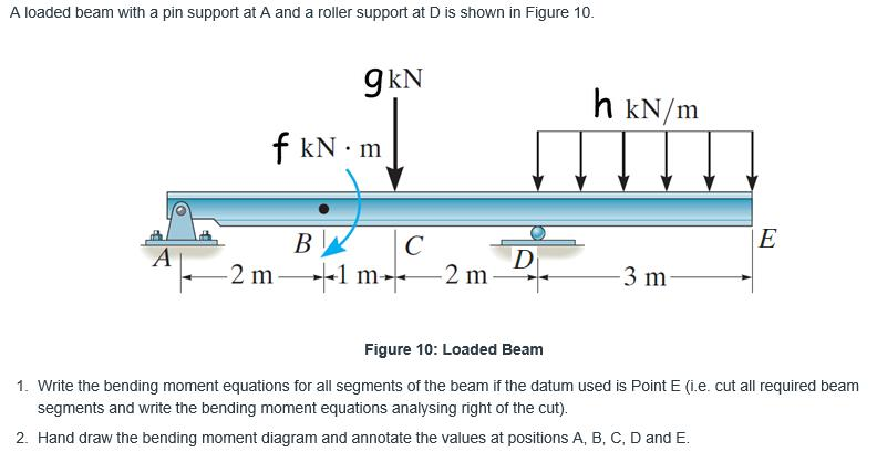
Solved A Loaded Beam With A Pin Support At A And A Roller Chegg Com
Draw the shear force and bending moment diagrams for the 3m length cantilever beam shown in Figure A.

. There are numerous typical. The following movies illustrate the implications of the type of support condition on the deflection behavior and on the location of maximum bending stresses of a beam supported at its ends. Abby the Exhibitionist Ch.
Assume the support at B is a roller and A and C are fixed. See a If the left portion makes an anticlockwise moment and the right portion of the section makes a Clockwise moment then it is hogging moment. Locknut Refill Tube Refill Clip Roller Clamp Hose Clamps 3 Adjustable Flapper.
To obtain numerical values of diagrams and support reactions you must Get an access code. Abby the Exhibitionist. One end of the beam is supported by hinge support and other one by roller support.
Simply supported beams consist of one span with one support at each end one is a pinned support and the other is a roller support. This beam carry load over the span which undergoes both shear stress and bending moment. Return to the starting position pushing your hips back and bending your knees until you bring the barbell back toward the floor.
Targus Metro Rolling Laptop Case Bag for Business Commuter with Durable Water Resistant Expandable Compartments Trolley Strap Padded Protection fits up to 16-Inch Notebook Screen Black TBR003US. I am using purity as my themeWhenever I want to log out I get the message that PurityM isnt installed or needs to be updated. It beam type undergoes both shear stress and bending moment.
Get an Access Code. This support allow to horizontal movement of beam. Determine the moments at A B and C and then draw the moment diagram.
This is a story of how a young woman becomes an exhibitionist Exhibitionist Voyeur 010221. 15 kN 15 kN 20 kN B. 5 p 22 u B wL R u u 2 52 t 88 u u.
EXPERIENCE. Fig1 Formulas for Design of Simply Supported Beam having. -Assign Fixed Hinged and Roller supports.
Roller supports can be added at any angle-Add point loads to any member or node at any angle. Trusses bridges and other structure member. A simply supported beam is the most simple arrangement of the structure.
Solid flapper frame resists bending for a secure seal. 4 Using Design Aid Tables. However the span size was chosen according to the distance of two adjacent brackets fixed on the teeth Figure 48This size is usually 14 mm Toyoizumi et.
Above and Beyond. Complete 13 sets of 812 reps. Simple Beams that are hinged on the left and fixed on the right.
PerforMAX Fill Valve Shank Washer Locknut Refill Tube Refill Clip Roller Clamp Hose Clamps PerformMAX High Performance Flapper. Why the Fixed End Moment FEM for BC is 3PL 16. But I still get the same message every time I try to log out.
The products are entirely designed and manufactured in Italy with high quality hardened steels. Given data in question UDL span length Cantilever beam To find out SFD BMD Q. Away from her husband her secretary lends a helping hand.
Figure 2 Shear and Bending Moment Diagrams. Above and Beyond Ch. A simply supported beam cannot have any translational displacements at its support points but no restriction is placed on rotations at the supports.
Bending Moment Diagram BMD Shear Force Diagram SFD Axial Force Diagram AFD Moment is positive when tension at the. Adjustable valve height and flapper arms fit most toilet models. But for the span BC we could see that B is the roller and C is the pinned connection theres no fixed support in the span BC.
I click on update. Here the bending moment is Positive. Its clear in the first figure that that when one end is fixed while the another end is pinned then the fixed end moment is 3PL 16.
The beam is supported at each end and the load is distributed along its length. For the simply supported beam subjected to the loading shown derive. 09 m 09 m09 m -3 m -3 m Prob.
Also add moment loads-Add uniform or linearly varying distributed loads at any angle to a member-Add internal pin connections to any member-Calculates internal forces due to support displacements. The ends of these beams are free to rotate and have no moment resistance. Three-point bending test Figure 54 has been done for a sample arch wire developed above with a fiber volume fraction of 45As of early 2000s there is no specific standard for the characterization of an arch wire.

Solved Problem 2 Determine The Reaction At The Roller Chegg Com
Three Member Frame Pin Roller Side Top Bending Moment

Three Member Frame Pin Roller Central Bending Moment

Draw The Shear Force And The Bending Moment Diagram Of The Beam Shown In The Figure Below The Support A Is Pin Support And B Is Roller Support Homework Study Com
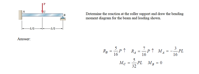
Solved Determine The Reaction At The Roller Support And Draw Chegg Com
Mechanical Engineering Is Bending Moment On Roller Supports At Beams Zero Engineering Stack Exchange
0 Response to "Bending Moment at Roller Support"
Post a Comment